Maharashtra State Board 12th Physics Solutions Chapter 13 AC Circuits
1. Choose the correct option.
i) If the RMS current in a 50 Hz AC circuit is 5A, the value of the current seconds after its value becomes zero is
(A) 5 A
(B) 5 A
(C) A
(D) A
Answer:
(B) 5 A
ii) A resistor of 500 Ω and an inductance of 0.5 H are in series with an AC source which is given by V = 100 sin (1000t). The power factor of the combination
(A)
(B)
(C) 0.5
(D) 0.6
Answer:
(A)
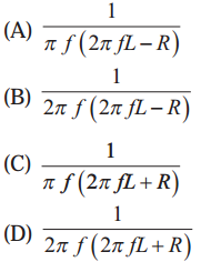
iii) In a circuit L, C & R are connected in series with an alternating voltage of frequency f. the current leads the voltage by 450. The value of C is
Answer:
(B)
iv) In an AC circuit, e and i are given by e = 150 sin (150t) V and i = 150 sin (150 t + ) A. the power dissipated in the circuit is
(A) 106W
(B) 150W
(C) 5625W
(D) Zero
Answer:
(C) 5625W
v) In a series LCR circuit the phase difference between the voltage and the current is 45°. Then the power factor will be
(A) 0.607
(B) 0.707
(C) 0.808
(D) 1
Answer:
(B) 0.707
2. Answer in brief.
i) An electric lamp is connected in series with a capacitor and an AC source is glowing with a certain brightness. How does the brightness of the lamp change on increasing the capacitance ?
Answer:
Impedance, Z = , where R is the resistance of the lamp, w is the angular frequency of AC and C is the capacitance of the capacitor connected in series with the AC source and the lamp. When C is increased, decreases. Hence, Z increases.
Power factor, cos Φ =
As Z increases, the power factor decreases.
Now, the average power over one cycle,
Pav= vrmsirmscos Φ
= Vrms cos Φ
=
∴ Pavdecreases as Z increases and cos Φ decreases.
As the current through the lamp decreases, the brightness of the lamp will decrease when C is increased.
ii) The total impedance of a circuit decreases when a capacitor is added in series with L and R. Explain why ?
Answer:
For an LR circuit, the impedance,
ZLR= , where XLis the reactance of the inductor.
When a capacitor of capacitance C is added in series with L and R, the impedance,
ZLCR= because in the case of an inductor the current lags behind the voltage by a phase angle of rad while in the case of a capacitor the current leads the voltage by a phase angle of rad. The decrease in net reactance decreases the total impedance (ZLCR< ZLR).
iii) For very high frequency AC supply, a capacitor behaves like a pure conductor. Why ?
Answer:
The reactance of a capacitor is XC= , where f is the frequency of the AC supply and C is the capacitance of the capacitor. For very high frequency, f, XCis very small. Hence, for very high frequency AC supply, a capacitor behaves like a pure conductor.
iv) What is wattless current ?
Answer:
The current that does not lead to energy consumption, hence zero power consumption, is called wattless current.
In the case of a purely inductive circuit or a purely capacitive circuit, average power consumed over a complete cycle is zero and hence the corresponding alternating current in the circuit is called wattless current.
[Note : In this case, the power factor is zero.]
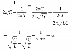
v) What is the natural frequency of L C circuit ? What is the reactance of this circuit at this frequency
Answer:
The natural frequency of LC circuit is ,
where L is the inductance and C is the capacitance. The reactance of this circuit at this frequency is
Solution & Step-by-Step Answer:
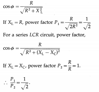
For a series LR circuit, power factor,
Solution & Step-by-Step Answer:
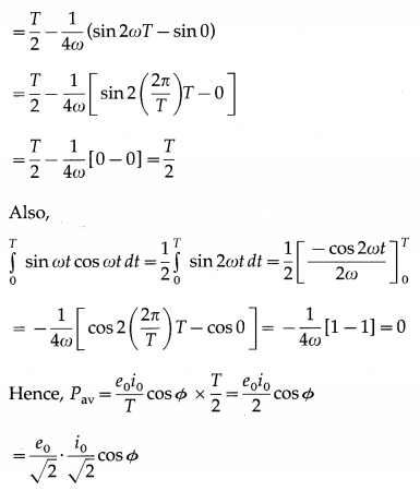
In an AC circuit containing only an ideal inductor, the current i lags behind the emf e by a phase angle of rad. Here, for e = e0 sin ωt, we have, i = i0 sin(ωt – ) Instantaneous power, P = ei = (e0 sin ωt) [i0 (sin ωt cos – cos ωt sin )] = – e0i0 sin ωt cos ωt as cos = 0 and sin = 1. Average power over one cycle, = erms irms cos Φ = erms irms (), where the impedance Z = . ∴ Pav = 0, i.e., the circuit does not dissipate power.
Solution & Step-by-Step Answer:
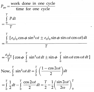
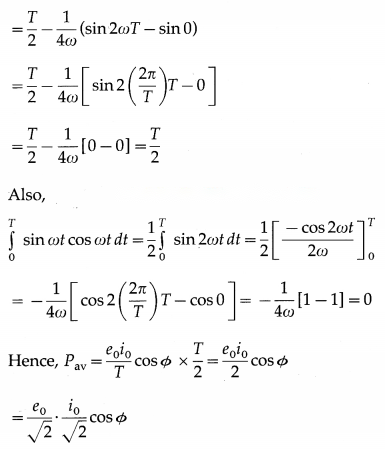
In an AC circuit containing only an ideal inductor, the current i lags behind the emf e by a phase angle of rad. Here, for e = e0 sin ωt, we have, i = i0 sin(ωt – ) Instantaneous power, P = ei = (e0 sin ωt) [i0 (sin ωt cos + cos ωt sin )] = – e0i0 sin ωt cos ωt as cos = 0 and sin = 1. Average power over one cycle, Pav = erms irms cos Φ = erms irms (), where the impedance Z = . ∴ Pav = 0, i.e., the circuit does not dissipate power.
Solution & Step-by-Step Answer:
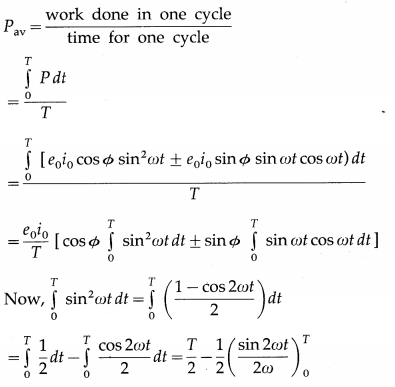
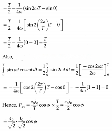
(a) Instantaneous power, P = ei = (e0 sin ωt) [i0 (sin ωt ± Φ)] = e0i0 sin ωt(sin ωt cos Φ ± cos ωt sin Φ) = e0i0 sin2 ωt ± e0i0 sin Φ sin ωt cos ωt Average power over one cycle, = erms irms cos Φ = erms irms (), where the impedance Z = .
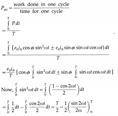
(b) Pav= ermsirmscos Φ
The factor cos Φ is called as power factor. For circuits used for transporting electric power, a low power factor means the power available on transportation is much less than ermsirmsIt means there is significant loss of power during transportation.
Solution & Step-by-Step Answer:
(a) The device Y is a capacitor. Its reactance is Xc = , where ω is the angular frequency of the applied emf and C is the capacitance of the capacitor.
(b)
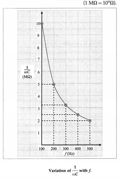
(c) XC= . Thus XC∝ , where f is the frequency of AC. Suppose C = pF
For f= 100 Hz, XC= 1 × 10⁷Ω = 10MΩ;
for f = 200 Hz, XC= 5 MΩ;
for f = 300 Hz, XC= MΩ;
for f = 400 Hz, XC= 2.5 MΩ
for f = 500 Hz, XC= 2 MΩ and so on
(d)
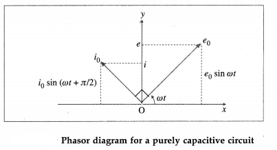
The phasor representing the peak emf (e0) makes an angle (ωt) in an anticlockwise direction with respect to the horizontal axis. As the current leads the voltage by 90°, the phasor representing the peak current (i0) is turned 90° anticlockwise with respect to the phasor representing emf e0. The projections of these phasors on the vertical axis give instantaneous values of e and i.
Solution & Step-by-Step Answer:
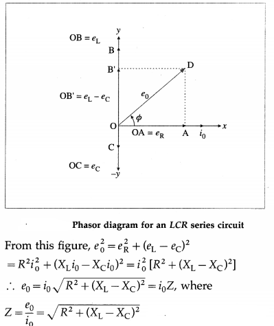
Figure shows an inductor of inductance L, capacitor of capacitance C, resistor of resistance R, key K and source (power supply) of alternating emf (e) connected to form a closed series circuit. We assume the inductor, capacitor and resistor to be ideal. As these are connected in series, at any instant, they carry the same current i = i0 sin ωt. The voltage across the resistor, eR = Ri, is in phase with the current. The voltage across the inductor, eL = XLi, leads the current by rad and that across the capacitor, eC = XCi, lags behind the current by rad. This is shown in the phasor diagram. is the effective resistance of the circuit. It is called the impedance.

Solution & Step-by-Step Answer:
(1) Resistance is opposition to flow of charges (current) and appears in a DC circuit as well as in an AC circuit. The term reactance appears only in an AC circuit. It occurs when an inductor and/or a capacitor is used.
(2) In a purely resistive circuit, current and voltage are always in phase.
When reactance is not zero, there is nonzero phase difference between current and voltage.
(3) Resistance does not depend on the frequency of AC.
Reactance depends on the frequency of AC. In case of an inductor, reactance increases linearly with frequency. In case of a capacitor, reactance decreases as frequency of AC increases; it is inversely proportional to frequency.
(4) Resistance gives rise to production of Joule heat in a component.
In a circuit with pure reactance, there is no production of heat.
Solution & Step-by-Step Answer:
Figure 13.8 shows an AC source, generating a voltage e = e0 sin ωt, connected to a key K and a pure inductor of inductance L to form a closed circuit. On closing the key K, an emf is induced in the inductor as the magnetic flux linked with it changes with time. This emf opposes the applied emf and according to the laws of electromagnetic induction by Faraday and Lenz, we have, e’ = -L ………………. (1) where e’ is the induced emf and i is the current through the inductor. To maintain the current; e and e’ must be equal in magnitude and opposite in direction.
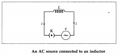
According to Kirchhoff’s voltage law, as the resistance of the inductor is assumed to be zero, we
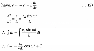
where C is the constant of integration. C must be time independent and have the dimension of current. As e oscillates about zero, i also oscillates about zero and hence there cannot be any time independent component of current.
∴ C = 0. ∴ i = –cos ωt = – sin( – ωt)
∴ i = sin(ωt – ) ……………. (3)
as sin (-θ) = – sin θ
From Eq. (3), ipeak= i0=
∴ i = i0sin(ωt – ) ………………. (4)
Comparison of this equation with e = e0sin ωt shows that e leads i by rad, i.e., the voltage is ahead of current by rad in phase.
Solution & Step-by-Step Answer:
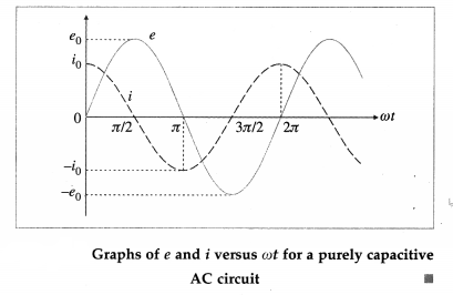
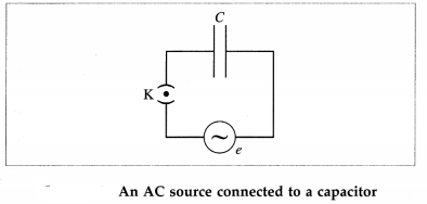
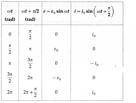
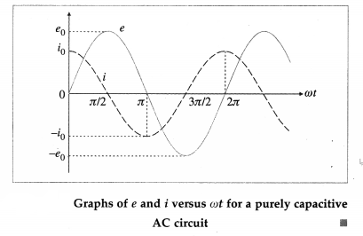
Figure 13.12 shows an AC source, generating a voltage e = e0 sin ωt, connected to a capacitor of capacitance C. The plates of the capacitor get charged due to the applied voltage. As the alternating voltage is reversed in each half cycle, the capacitor is alternately charged and discharged. If q is the charge on the capacitor, the corresponding potential difference across the plates of the capacitor is V = ∴ q = CV. q and V are functions of time, with V = e = e0 sin ωt. The instantaneous current in the circuit is i = (CV) = C = C (e0 sin ωt) = ωC e0 cos ωt ∴ i = where i0 = is the peak value of the current. Table gives the values of e and i for different values of cot and Fig shows graphs of e and i versus ωt. i leads e by phase angle of rad.
Solution & Step-by-Step Answer:
Data : f = 50 Hz, irms = 5 A, t = s The peak value of the current, i0 = irms = (5)(1.414) = 7.07 A = i0sin (2πft) = 7.07 sin [2π(5o) ()] = 7.07 sin () = (7.07)(0.5) = 3.535 A This is the required current.
Solution & Step-by-Step Answer:
Data: Power (Vrms irms) = 100 W, Vrms = 220V, f = 50 Hz The rms current through the bulb, irms = = 0.4545 A The resistance of the bulb, R = = (22) (22) = 484 Ω
Solution & Step-by-Step Answer:
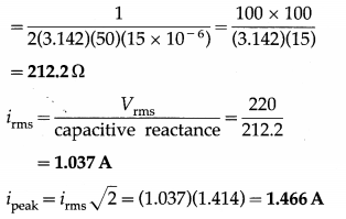
Data : C = 15 µF = 15 × 10-6 F, Vrms = 220V, f = 50 Hz, The capacitive reactance = If the frequency is doubled, the capacitive reactance will be halved and the current will be doubled.
Solution & Step-by-Step Answer:
Data : L = 2H, i0 = 0.25 A, f = 60 Hz, π = 3.142 ωL = 2πfL = 2(3.142)(60)(2) = 754.1 Ω The effective potential difference across the inductor = ωLirms = ωL = = 133.3 V
Solution & Step-by-Step Answer:
Data: e = 220 sin 100 πt, L = ()H Comparing e = 220 sin 100 πt with e = e0 sin ωt, we get ω = 100 π ∴ ωL = (100 π) () = 100 Ω ∴ The instantaneous current through the circuit = i = sin(100 πt – ) = sin (100 πt – ) = 2.2 sin (100 πt – ) in ampere [assuming that e is in volt.] irms = = 1.556 A is the reading of the AC galvanometer connected in the circuit.
Solution & Step-by-Step Answer:
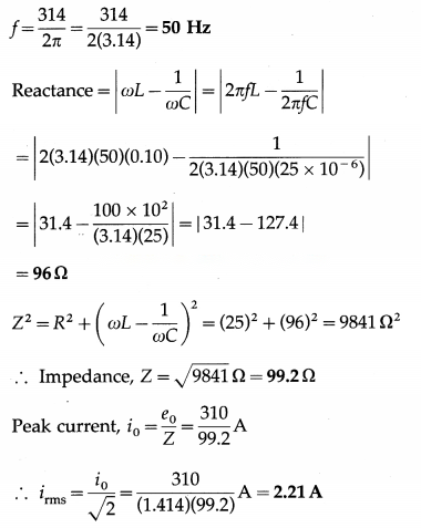
Data: C = 25 µF = 25 × 10-6F, L = 0.10H, R = 25 Ω, e = 310 sin (314 t) [volt] Comparing e = 310 sin (314 t) with e = e0 sin (2πft), we get, the frequency of the alternating emf as cos Φ = = 0.2520 ∴ The phase angle, Φ = cos-1(0.2520) = 75.40° = 1.316 rad
Solution & Step-by-Step Answer:
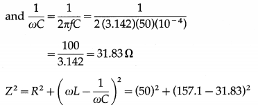
Data : C = 100 µF = 100 × 10-6 F = 10-4 F, R = 50 Ω, L = 0.5H, f = 50 Hz, Vrms = 110 V ∴ ωL = 2πfL = 2 (3.142)(50)(0.5) = 157.1 Ω 2500 + 15700 = 18200 Ω2 ∴ Impedance, Z = Ω = 134.9 Ω The rms value of the current in the circuit, irms = = 0.8154 A
Solution & Step-by-Step Answer:
Data : R = 10 Ω, power factor = 0.5, f = 100 Hz Power factor = ∴ 0.5 = ∴ C = = = 3.182 × 10⁻⁴ F This is the capacity of the capacitor.
Solution & Step-by-Step Answer:
Data : f = 50 Hz, i = ∴ i = i0 sinωt ∴ sinωt = ∴ ωt = rad ∴ 2πft = ∴ t = = = 2.5 × 10⁻³ s This is the required time.
Solution & Step-by-Step Answer:
Data : fr = 106 Hz, L = 101.4 × 10⁻⁶ H = = 2.497 × 10⁻¹⁰ F = 249.7 × 10⁻¹² F = 249.7 picofarad This is the value of the capacity.

Solution & Step-by-Step Answer:
Data: C = 10 µF = 10 × 10-6F = 10-5F, L = 100mH = 100 × 10-3 H = 10-1 H, V = 25V For reference, see the solved example (8) above. CV2 = Li2 ∴i2 = ∴i = 25 × 10-2 A = 0.25 A This is the maximum current in the coil.
Solution & Step-by-Step Answer:
Data: C = 100 µF = 100 × 10-6 F = 10-4 F, V = 50V, i = 5A The energy stored in the electric field in the capacitor = CV2 The energy stored in the magnetic field in the inductor = Li2 Here, CV2 = Li2 ∴ L = C ∴ L = C = 10-4 × 102 = 10-2H This is the value of the inductance.