Maharashtra State Board 11th Physics Solutions Chapter 9 Optics
1. Multiple Choise Questions
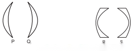
2. Answer the following questions.

ii. Concave mirror produces diminished image when object is placed:
iii. Concave mirror produces magnified image when object is placed:
ii. In case of spherical mirrors (excluding small aperture spherical mirrors), rays farther from the principle axis do not remain parallel to the principle axis. Thus, the third assumption is not followed and the focus gradually shifts towards the pole.
iii. The relation (f = ) giving a single point focus is not followed and the image does not get converged at a single point resulting into a distorted or defective image.
iv. This defect arises due to the spherical shape of the reflecting surface.
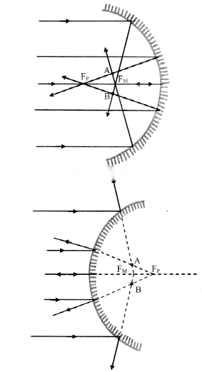
Remedies for Spherical Aberration:
ii. A stick or pencil kept obliquely in a glass containing water appears broken as its part in water appears to be raised.
iii. As the speed of light is different in two media, the rays of light coming from water undergo refraction at the boundary separating two media.
iv. Consider speed of light to be v in water and c in air. (Speed of light in air ~ speed of light in vacuum)
∴ refractive index of water = = =
v. Relative refractive index of a medium 2 is the refractive index of medium 2 with respect to medium 1 and it is defined as the ratio of speed of light v1in medium 1 to its speed v1in medium 2.
∴ Relative refractive index of medium 2,
1n2=
vi. Consider a beaker filled with water of absolute refractive index n1kept on a transparent glass slab of absolute refractive index n2.
vii. Thus, the refractive index of water with respect to that of glass will be,
nw2= = =
ii. Mirage results from the refraction of light through a non-uniform medium.
iii. On a hot day the air in contact with the road is hottest and as we go up, it gets gradually cooler. The refractive index of air thus decreases with height. Hot air tends to be less optically dense than cooler air which results into a non-uniform medium.
iv. Light travels in a straight line through a uniform medium but refracts when traveling through a non-uniform medium.
v. Thus, the ray of light coming from the top of an object get refracted while travelling downwards into less optically dense air and become more and more horizontal as shown in Figure.
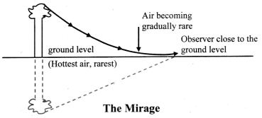
vi. As it almost touches the road, it bends (refracts) upward. Then onwards, upward bending continues due to denser air.
vii. As a result, for an observer, it appears to be coming from below thereby giving an illusion of reflection from an (imaginary) water surface.
ii. The angle of incidence in the denser medium must be greater than critical angle for the given pair of media.
Total internal reflection in optical fibre:
iii. Consider an optical fibre made up of core of refractive index n1and cladding of refractive index n2such that, n1> n2.
iv. When a ray of light is incident from a core (denser medium), the refracted ray is bent away from the normal.
v. At a particular angle of incidence icin the denser medium, the corresponding angle of refraction in the rarer medium is 90°.
vi. For angles of incidence greater than ic, the angle of refraction become larger than 90° and the ray does not enter into rarer medium at all but is reflected totally into the denser medium as shown in figure.

critical angle of incidence and obtain an expression:
i. Critical angle for a pair of refracting media can be defined as that angle of incidence in the denser medium for which the angle of refraction in the rarer medium is 90°.
ii. Let n be the relative refractive index of denser medium with respect to the rarer.
iii. Then, according to Snell’s law,
n = = =
∴ sin (ic) =

Working:

Advantages of optical fibre communication over electronic communication:
Working:
ii. P is the pole and X’PX is the principal axis. A point object O is at a distance u from the pole, in the medium of refractive index n1.
iii. In order to minimize spherical aberration, we consider two paraxial rays.
iv. The ray OP along the principal axis travels undeviated along PX. Another ray OA strikes the surface at A.
v. As n1< n2, the ray deviates towards the normal (CAN), travels along AZ and real image of point object O is formed at I.
vi. Let α, β and γ be the angles subtended by incident ray, normal and refracted ray with the principal axis.
∴ i = (α + β) and r = (β – γ)
vii. As, the rays are paraxial, all the angles can be considered to be very small.
i.e., sin i ≈ i and sin r ≈ r
Angles α, β and γ can also be expressed as,
viii. According to Snell’s law,
n1sin (i) = n2sin (r)
For small angles, Snell’s law can be written
as, n1i = n2r
∴ n1(α + β) = n2(β – γ)
∴ (n2– n1)β = n1α + n2γ
Substituting values of α, β and γ, we get,
(n2– n1) = n1() + n2()
∴ = –
Assumptions: To derive an expression that relates object and image distances with the radius of curvature for a point object, the two rays considered are assumed to be paraxial thus making the angles subtended by incident ray, normal and refracted ray with the principal axis very small.
ii. Assuming the lens to be thin, P is the common pole for both the surfaces. O is a point object on the principal axis at a distance u from P.
iii. The refracting surface facing the object is considered as first refracting surface with radii R1.
iv. In the absence of second refracting surface, the paraxial ray OA deviates towards normal and would intersect axis at I1. PI1= V1is the image distance for intermediate image I1.
Before reaching I1, the incident rays (AB and OP) strike the second refracting surface. In this case, image I1acts as a virtual object for second surface.
vii. For second refracting surface,
n2= 1, n1= n, R = R2, u = v1and PI = v
∴ ………… (2)
viii. Adding equations (1) and (2),
(n – 1)
For object at infinity, image is formed at focus, i.e., for u = ∞, v = f. Substituting this in above equation,
…………. (3)
This equation in known as the lens makers’ formula.
ix. Since the equation can be used to calculate the radii of curvature for the lens, it is called the lens makers’ equation.
x. The numeric value of focal length f and radius of curvature R is same under following two conditions:
Case I:
For a thin, symmetric and double convex lens made of glass (n = 1.5), R1is positive and R2is negative but, |R1| = |R2|.
In this case,
∴ f = R
Case II:
Similarly, for a thin, symmetric and double concave lens made of glass (n = 1.5), R1is negative and R2is positive but, |R1| = |R2|.
In this case,
∴ f = -R or |f| = |R|
3. Answer the following questions in detail.
ii. The refractive index of material depends on the frequency of incident light. Hence, for different colours, refractive index of material is different.
iii. For an obliquely incident ray, the angles of refraction are different for each colour and they separate as they travel along different directions resulting into angular dispersion.
iv. When a polychromatic beam of light is obliquely incident upon a plane parallel transparent slab, emergent beam consists of all component colours separated out.
v. In this case, these colours are parallel to each other and are also parallel to their initial direction resulting into lateral dispersion
ii. For any two component colours, angular dispersion is given by,
δ21= δ2– δ1
iii. For white light, we consider two extreme colours viz., red and violet.
∴ δVR= δV– δR
iv. For thin prism,
δ = A(n – 1)
δ21= δ2– δ1
= A(n2– 1) – A(n1– 1) = A(n2– n1)
where n1and n2are refractive indices for the two colours.
v. For white light,
δVR= δV– δR
= A(nV– 1) – A(nR– 1) = A(nV– nR).
It is measured for any two colours as the ratio of angular dispersion to the mean deviation for those two colours. Thus, for the extreme colours of white light, dispersive power is given by,
(ii) Explain the formation of a primary rainbow. For which angular range with the horizontal is it visible?
Answer:
i. A ray AB incident from Sun (white light) strikes the upper portion of a water drop at an incident angle i.
ii. On entering into water, it deviates and disperses into constituent colours. The figure shows the extreme colours (violet and red).
iii. Refracted rays BV and BR strike the opposite inner surface of water drop and suffer internal reflection.
iv. These reflected rays finally emerge from V’ and R’ and can be seen by an observer on the ground.
v. For the observer they appear to be coming from opposite side of the Sun.
vi. Minimum deviation rays of red and violet colour are inclined to the ground level at θR= 42.8° ≈ 43° and θV= 40.8 ≈ 41° respectively. As a result, in the rainbow, the red is above and violet is below.
(iii) Explain the formation of a secondary rainbow. For which angular range with the horizontal is it visible?
Answer:
i. A ray AB incident from Sun (white light) strikes the lower portion of a water drop at an incident angle i.
ii. On entering into water, it deviates and disperses into constituent colours. The figure shows the extreme colours (violet and red).
iii. Refracted rays BV and BR finally emerge the drop from V’ and R’ after suffering two internal reflections and can be seen by an observer on the ground.
iv. Minimum deviation rays of red and violet colour are inclined to the ground level at θR≈ 51° and θV≈ 53° respectively. As a result, in the rainbow, the violet is above and red is below.
(iv) Is it possible to see primary and secondary rainbow simultaneously? Under what conditions?
Answer:
Yes, it is possible to see primary and secondary rainbows simultaneously. This can occur when the centres of both the rainbows coincide.
(ii) What is achromatism? Derive a condition to achieve achromatism for a lens combination. State the conditions for it to be converging.
Answer:
i. To eliminate chromatic aberrations for extreme colours from a lens, either a convex and a concave lens in contact or two thin convex lenses with proper separation are used.
ii. This combination is called achromatic combination. The process of using this combination is termed as achromatism of a lens.
iii. Let ω1and ω2be the dispersive powers of materials of the two component lenses used in contact for an achromatic combination.
iv. Let V, R and Y denote the focal lengths for violet, red and yellow colours respectively.
v. For lens 1, let
K1= (–)1and K2= (–)2
vi. For the combination to be achromatic, the resultant focal length of the combination must be the same for both the colours,
This is the condition for achromatism of a combination of lenses.
Condition for converging:
For this combination to be converging, fY must be positive.
Using equation (3), for fYto be positive, (fY)1< (fY)2⇒ ω1< ω2
ii. A single point focus in case of lenses is possible only for small aperture spherical lenses and for paraxial rays.
iii. The rays coming from a distant object farther from principal axis no longer remain parallel to the axis. Thus, the focus gradually shifts towards pole.
iv. This defect arises due to spherical shape of the refracting surface, hence known as spherical aberration. It results into a blurred image with unclear boundaries.
v. As shown in figure, the rays near the edge of the lens converge at focal point FM. Whereas, the rays near the principal axis converge at point FP. The distance between FMand FPis measured as the longitudinal spherical aberration.
vi. In absence of this aberration, a single point image can be obtained on a screen. In the presence of spherical aberration, the image is always a circle.
vii. At a particular location of the screen (across AB in figure), the diameter of this circle is minimum. This is called the circle of least confusion. Radius of this circle is transverse spherical aberration.
Methods to eliminate/reduce spherical aberration in lenses:
i. Cheapest method to reduce the spherical aberration is to use a planoconvex or planoconcave lens with curved side facing the incident rays.
ii. Certain ratio of radii of curvature for a given refractive index almost eliminates the spherical aberration. For n = 1.5, the ratio is
= and for n = 2, =
iii. Use of two thin converging lenses separated by distance equal to difference between their focal lengths with lens of larger focal length facing the incident rays considerably reduces spherical aberration.
iv. Spherical aberration of a convex lens is positive (for real image), while that of a concave lens is negative. Thus, a suitable combination of them can completely eliminate spherical aberration.
ii. The linear magnification is the ratio of the size of the image to the size of the object.
iii. When the distances of the object and image formed are very large as compared to the focal lengths of the instruments used, the magnification becomes infinite. Whereas, the magnifying power being the ratio of angle subtended by the object and image, gives the finite value.
iv. For example, in case of a compound microscope,
Mmin= = = 5 and Mmax= 1 + = 6
Hence image appears to be only 5 to 6 times bigger for a lens of focal length 5 cm.
For Mmin= = 5, V = ∞
∴ Lateral magnification (m) = = ∞
Thus, the image size is infinite times that of the object, but appears only 5 times bigger.
ii. Figure (b) shows a convex lens forming erect, virtual and magnified image of the same object, when placed within the focus.
iii. The visual angle p of the object and the image in this case are the same. However, this time the viewer is looking at the image which is not closer than D. Hence the same object is now at a distance smaller than D.
iv. Angular magnification or magnifying power, in this case, is given by
M = =
For small angles,
M = ≈ = =
v. For maximum magnifying power, the image should be at D. For thin lens, considering thin lens formula.
ii. Visual angle of the final image is p and its position can be adjusted to be at D. However, under normal adjustments, the final image is also at infinity making a greater visual angle than that of the object.
iii. The parallax at the cross wires can be avoided by using the telescopes in normal adjustments.
iv. Objective of focal length f0focusses the parallel incident beam at a distance f0from the objective giving an inverted image AB.
v. For normal adjustment, the intermediate image AB forms at the focus of the eye lens. Rays refracted beyond the eye lens form a parallel beam inclined at an angle β with the principal axis.
vi. Angular magnification or magnifying power for telescope is given by,
M = ≈ = =
vii. Length of the telescope for normal adjustment is, L = f0+ fe.
ii. In case of compound microscope,
M =
Thus, in order to increase m0, we need to decrease u0. Thereby, the object comes closer and closer to the focus of the objective. This increases v0and hence length of the microscope. Therefore, mQ can be increased only within the limitation of length of the microscope.
iii. In case of telescopes,
M =
Where f0= focal length of the objective
fe= focal length of the eye-piece
Length of the telescope for normal adjustment is, L = f0+ fe.
Thus, magnifying power of telescope can be increased only within the limitations of length of the telescope.
4. Solve the following numerical examples
ii. For θ2= 36°
n2= = 10
As n2is even integer, N2= (n2– 1) = 9
iii. For θ3= 40°
n3= = 9
As n3is odd integer.
Number of images seen (N3) = n3– 1 = 8
(if the object is placed at the angle bisector) or Number of images seen (N3) = n3= 9
(if the object is placed off the angle bisector)
iv. For θ4= 45°
n4= = 8
As n4is even integer,
N4= n4– 1 = 7
As, the light ray undergo total internal reflection at P, the ray BP may be incident at critical angle.
For a Pythagorean triangle with sides in ratio 3 : 4 : 5 the angle opposite to side 3 units is 37° and that opposite to 4 units is 53°.
Thus, from figure, we can say, in ΔBAP
∠ABP = 53°
∠BPN = ic= 53°
∴ nglass= = ≈ =
∴ Refractive index (n) of the slab is
From symmetry, ∆PDQ is also a Pythagorean triangle with sides in ratio QD : PD : PQ = 3 : 4 : 5.
PD = 2 cm ⇒ QD = 1.5 cm.
As critical angle is ic= 53° and angle of incidence at Q, ∠PQN = 37° is less than critical angle, there will be partial internal reflection at Question
11th Physics Digest Chapter 9 Optics Intext Questions and Answers
Can you recall? (Textbook rage no 159)
What are laws of reflection and refraction?
Answer:
Laws of reflection:
a. Reflected ray lies in the plane formed by incident ray and the normal drawn at the point of incidence and the two rays are on either side of the normal.
b. Angles of incidence and reflection are equal (i = r).
Laws of refraction:
a. Refracted ray lies in the plane formed by incident ray and the normal drawn at the point of incidence; and the two rays are on either side of the normal.
b. Angle of incidence (θ1) and angle of refraction (θ2) are related by Snell’s law, given by, n1sin θ1= n2sin θ2where, n1, n2= refractive indices of medium 1 and medium 2 respectively.
Can you recall? (Textbook page no. 159)